I’m building a pulse monitor from an infrared LED, a photodiode, and a breadboard. It’s a way to understand what happens before a biosignal becomes a number on a screen.
The long-term interest is neurotechnology. The immediate problem is much smaller: shine light through a finger, collect what comes out the other side, and find the heartbeat hiding in it.
The finger is part of the circuit.
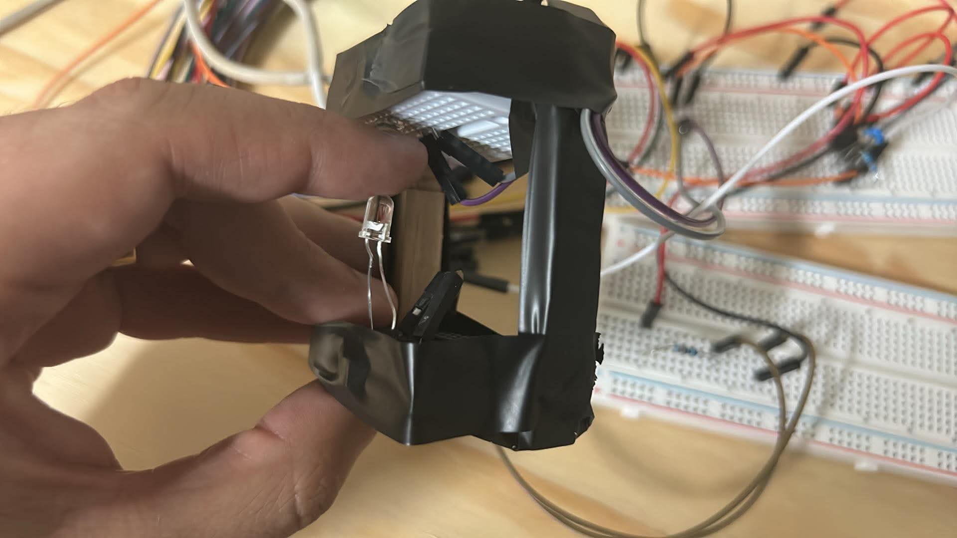
The optical setup matters as much as the electronics. The LED and detector need to stay opposite each other, with the finger held reasonably still. A loose connection or a bit of movement can change the reading. So can the room lights.
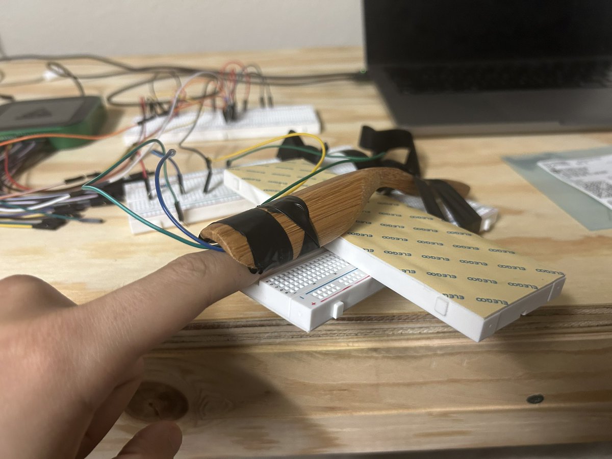
That’s what the tape and improvised holder are doing in these photos: keeping the geometry steady and blocking some of the unwanted light. It’s a very physical problem for something that eventually becomes a waveform.
Light, current, voltage.
The build plan pairs a 940 nm infrared LED with a BPW34 photodiode. The photodiode produces a current that changes with the amount of light reaching it. Pulsing blood volume changes the light transmitted through the finger, adding a small variation to a much larger background signal.
- 01IlluminateIR light through a finger
- 02DetectPhotodiode current
- 03AmplifyCurrent becomes voltage
- 04FilterKeep the pulse variation
A transimpedance amplifier converts that current into a voltage. In an ideal example, 5 microamps through a 100-kilohm feedback resistor gives a 0.5-volt change. Increasing the resistance makes the signal larger, but it also makes it easier to run out of amplifier headroom. More gain isn’t automatically better.
Give the light a signature.
A later stage in the plan switches the LED at 1 kHz. The detector signal can then be compared with that known timing to recover the part associated with the LED. The heartbeat becomes a slow change in the strength of that fast signal. This is synchronous detection—the same general idea used to pick weak signals out of a noisy measurement.
The photos show the breadboard stage. Clean waveform capture, ambient-light rejection, and a soldered version are goals in the build plan; I’m not presenting them here as completed measurements. This is an electronics learning project, not a diagnostic device.
Component reference: Vishay BPW34 datasheet. The circuit details above come from my build plan; the photos are from the actual project.